Evolution v-tail - Introduction
For the coming season a new version of the Evolution with a V-Tail was developed.The contest model Evolution is made for the F3B model category.
Electro modification for the Evolution model.

Description
The preceding X-Tail version has fulfilled the goal for which it was designed. This is shown mainly by the victory of Andreas Böhlen in the Eurotour Contest in Salzburg and Hans Rossman at the Hohe Wand 2008 and many others placed in the contests. The whole conception of the model was kept. The V-Tail is made of 2 pieces. The standard version is made for the 2.4 GHz system.
Development
The airfoil is from Max Steidle (Wing: M 1580 and M1585, other: M08), who also made airfoils for models such as the Crossfire or Tool. He deserves acknowledgments. The Evolution is the first serial produced model with no control horns on the outside To reach the maximal precision in the prototype production, a 3D mill cutter was used. The programs were made with the help of our webmaster, Michal Michna.
Evolution v-tail - Details

| Category: | F3B |
| Conception: | Two part wing, two part elevator, v-tail |
| Wing span: | 3140 mm |
| Length: | 1470 mm |
| Wing area: | 59,58 dm2 |
| V-tail angle: | ~ 100° |
| V-tail area: | 5,60 dm2 |
| Wing airfoil: | M 1580 and M1585 |
| Elevator airfoil: | M08 |
| Weight: | from 2050g |
| Ballast: | 900g |
| Maximum servo width: | wing center: 12 mm (Futaba S3150 or Airtronics 94761Z) , wing tip: 12 mm (Futaba S3150), fuselage: 12 mm (Graupner 3871) |
| Construction: | |
| Wing | carbon-rohacel-glass or carbon-rohacel-carbon |
| Spar | UMS Carbon |
| Tailplane | glass-balsa-glass |
| Fuselage | carbon-glass |
Drawing

Evolution v-tail - Performance analysis
We have calculated the performance of the Evolution V-Tail model using the XFoil program. We hope that this knowledge will allow better settings for your model and will contribute to improving the properties for a new model. We plan to compare the calculated results with the actual parameters of the model using a barometric altimeter and GPS logger as soon as possible. So far, however, the results appear to be remarkably accurate (for example minimum sink rate).
Results were calculated for a model weight from 2200 grams to 3400 grams with 400 grams resolution. It appears that for distance and speed task, more weight means a better outcome. The graphs also show the maximum glide ratio and maximum flight efficiency. For distance task it is good to move between the maximum of these variables. For Evolution model the trim speed is almost the same as the speed for maximum glide ratio. All calculations are for a model with control surfaces (v-tail, elevator, ailerons, flaps) in neutral position.
Computer analysis model performance
Descent rate
 |
 |
 |
| Full scale velocity | Low velocity | High velocity |
Flight effeciency
 |
 |
 |
| Full scale velocity | Low velocity | High velocity |
Glide ratio
 |
 |
 |
| Full scale velocity | Low velocity | High velocity |
Trim speed and forward speed
 |
 |
| Trim speed - all control surfaces (elevator,aileron, flaps) are in neutral, then model have stable speed where curve intersect x-axis on graph. | Graph shows the dependence of the flight speed to the forward speed (x-axis projection) |
Airflow visualisation at speed 10m/s
 |
 |
| Perspective view | Left view |
 |
 |
| Back view | Top view |
Presure visualisation at speed 10m/s
 |
 |
| Presure visualisation | Presure and airflow |
Drag and lift distribution at speed 10m/s
 |
 |
| Induced drag and velocity drag distribution | Wing and V-tail lift distribution |
Evolution v-tail - Performance
Custom color scheme desinger
Evolution v-tail - Mounting
v-tail driving system
 |
 |
 |
 |
 |
 |
 |
 |
 |
 |
||
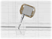
Torsion "RDS" servo drive...

Thin and precision servo driving surfaces. Instalation instruction...
-
To form the cogwheel of the servo into the aluminium use a good liquid mould-release. You can use slightly thickened Epoxy for this.


-
You have two different bended steel. The more bended (55 deg.) is for flap and the other one (40 deg) for aileron.
-
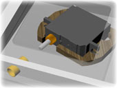
First you have to fix the servo-mount in the wing. Make a drawing on the wing like shown on the picture and glue the servo mount in the right position.


-
Next step is to glue the brass-tube into the bar.


-
Last step is to glue the bended steel into the aluminium. To gauge it on the right place you take a long time-epoxy and mount it in the wing. Then you must move the flap up and down two or three times and the steel will gauge automaticly. Fix the flap in a neutral position and wait 12 hours. Make sure that the little screw on the aluminium is on the upper side !!!!


-
After all use a teflon-grease on the steel and the slot. This helps to minimize abrasion and radial clearance in the future.


For the installation of Futaba servos S3150/S3155 for the RDS linkage we recommend these servo frames: http://www.rcsolutions.ch/index.php?show=64

Evolution v-tail - Settings
Settings table for EVOLUTION
| Trim positions | Flaps | Ailreons | Elevator | Rudder | ||
| Normal | 0 | 0 | 0 | 0 | ||
| Termic | 3 | 0,5 to flap | 0 | 0 | ||
| Speed | 0 | 0 | 0,7 | 0 | ||
| Start | 14 | 1 to flap | 0 | 0 | ||
| Butterfly | max down | 5 | 4 | 0 | ||
| Deflections | Flaps | Ailreons | Elevator | Rudder | ||
| Normal | 5/3 | 16/10 | 7/7 | 8/10 | ||
| Termic | 0 | 13/5 | 7/7 | 8/10 | ||
| Speed | 6/4 | 20/13 | 6/6 | 0 | ||
| Start | 0 | 20/2 | 7/7 | 10/12 | ||
| Butterfly | 0 | 20/12 | 7/7 | 8/10 | ||
| Wing mix | Elevator->Flaps+Ailreons | Ailreons->Rudder | ||||
| Normal | 4+3 | 3 | ||||
| Termik | - | 7 | ||||
| Speed | 4+3 | 1 | ||||
| Butterfly | - | 8 | ||||
| Towhook: 122 mm from end of cabin. | ||||||
| Center of gravity: from the leading edge 99 mm | ||||||
| up deflection/down deflection | ||||||
Settings templates
EVOLUTION wing settings template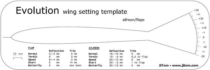 EVOLUTION v-tail elevator settings template

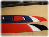
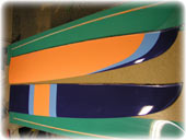
Evolution v-tail - Pictures
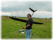
Final model
 |
 |
 |
 |
 |
Jiri Tuma training day - 21.6.2009
 |
 |
 |
 |
 |
 |
 |
 |
 |
 |
CAD - CAM pre-production form
 |
 |
 |
 |
 |
 |
 |
 |
 |
 |
||
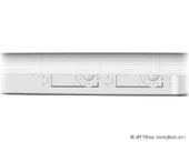
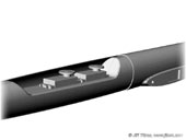
Virtual testing servos in fuse
 |
 |
 |
 |
 |
 |
||
Production first prototype models
 |
 |
 |
 |
 |
 |
 |
 |
 |
|||
Evolution v-tail - Results
Jiri Tuma training flights, altitude logs - 10.6.2009
Maximum is 343 meters! Average cca 300 meters. Wind aprox. 4-5 m/s.

Evolution v-tail - Reference
NEW Kanoh's RC Sailplane structure (japanese):
Evolution cross-tail article - http://model-sailplane.dialog.jp/evolution01.html|
Photo 1|
Photo 2|
Photo 3|
Photo 4|
Photo 5|
Photo 6
Other Evolution cross-tail article - http://model-sailplane.dialog.jp/evolution_2-01.html |
Photo 1|
Photo 2|
Photo 3
Video from Evolution flight:
http://www.dailymotion.com/video/x5bdx6_evolution-f3b_sport
Evolution on discusion:
http://www.rc-network.de/forum/showthread.php?t=111521
http://www.rcgroups.com/forums/showthread.php?t=783508
Evolution completion:
http://pierre.rondel.free.fr/images2/Evolution/EvolutionF3B.htm
Evolution in aufwind:
http://www.aufwind-magazin.de/redaktion/Evolution_607/index.html
Evolution v-tail - Prices
Pricelist, model versions and order
